
My Ender 3 had a Creality v 1.1.3 board with A4988 drivers which drive the motors with a fair bit of noise. Trinamic offer two drop-in replacements, the TMC2208 and TMC2209, so a couple of months ago i thought I’d try swapping out the drivers instead of buying a replacement board and drivers. I had three spare new TMC2208s too, so this option was free!
Originally I thought swapping out the X,Y and E would be best, as these three drivers are the ones that are most active, however after swapping the drivers I found that Marlin’s linear advance doesnt play nicely with the TMC2208 and I couldnt get any filament to extrude, so I swapped the E and Z axis in my Marlin config, swapped the plugs over on the board and everything worked fine. Details on how to perform this upgrade can be found in the TCM2208 Application Note AN045 (on this page) – pretty much just a case of swapping the chip, the cap on pins 4 & 5 from 0.1uf to 0.022uf, removing the resistors from pins 11 & 12 and re-setting the v-ref.
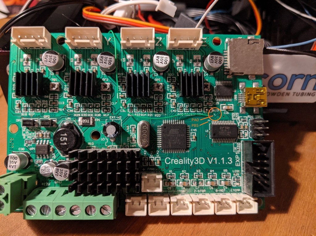
Fast forward to yesterday, I thought why not remove the connections to the SD card slot which I havent used in months, and use the newly available pins on the mcu to connect to the uart pins on the TMC2208s, it was a simple case of cutting 6 traces and adding three jumper wires, it took longer to get the board in and out of the printer than it did to do the mod work! You could also just cut the traces for PDN_UART on each chip, remove the IC U2, a 74HC541, (or lift pin 1 and pull it high) and connect to the pins on the ISP header instead of cutting the traces for PB5, PB6 & PB7 if you to cut less traces.
If you have the 1.1.4 or 1.1.5 with TMC2208s already on then this mod should also work, the boards look very similar but I’d double check the traces to cut with a multimeter first!
This is the front of the board showing the required trace cut and front side connection:
This is the back of the board, showing trace cuts and connections. Also visible is the beefed up ground connection – the white wire to the right and the always-on board fan – the trace cut and solder bridge at the bottom.

I made the following connections:
- X axis UART to pin 1/PB5 on the MCU
- Y axis UART to pin 37/PA0 on the MCU
- Z(E Driver) axis UART to pin 3/PB7 on the MCU
Bear in mind I only have TMC2208s on X,Y and Z (using the E driver), if you plan on doing this to your Z axis as well you will need to cut the circled un-cut trace to another spare pin, I suspect that PB6/PA2 will work fine – PA2 is the bottom pin on the EXT-A2 connector.
I tried PB6 for my Y axis at first but couldnt get it to work, it seems that it was the connection to the via for the TMC2208 UART pin that was the issue – I might have been a bit too vigorous when scraping the solder mask from the trace and broke the via. I manage to get the connection working by poking a piece of wire down the via before soldering it, which seemed to work – this was after moving the other end of the connection from PB6 to PA0). I had the board in the printer, connected and working, so I left it as is – if i have the board out in the future i’ll move the PA0 connection back to PB6 and update this post.
To get this working with klipper you’ll just need to add the following to your printer.cfg (might need to change the x,y,z uart_pin settings if you use other pins on the mcu)
[tmc2208 stepper_x]
uart_pin: PB5
microsteps: 16
run_current: 0.800
hold_current: 0.500
stealthchop_threshold: 250

[tmc2208 stepper_y]
uart_pin: PA0
microsteps: 16
run_current: 0.800
hold_current: 0.500
stealthchop_threshold: 250

[tmc2208 stepper_z]
uart_pin: PB7
microsteps: 16
run_current: 0.650
hold_current: 0.450
stealthchop_threshold: 30
Another way of possibly doing this in klipper would to make the trace cuts for the PDN_UART connections, connect these traces to an arduino and add an extra mcu entry to the printer.cfg, like in sample-multi-mcu.cfg in the klipper repo on github, you’ll then just need to prefix the pin names with the name of the mcu in your printer.cfg. I had a quick chat with the people on the klipper discord who confirmed this should work fine and would retain the use of the sd card.

First of all thank you soo much!!,I am from Arequipa, Peru and here is impossible to get another board without paying 3 times more than eBay, and a lot of sellers don’t send thing here, so I don’t have a lot of options, so I tried this and I can confirm this works on the Creality 1.1.5 silent board just make sure that the soldering in not making contact with another nearest via that you could have scratched, and I recommend who ever try this to make it work with marlin first before going to klipper, that is what I did.
LikeLike
Thanks for the kind comment, glad it worked for you!
LikeLike
by the way , this is what needs to be changed to make it work in marlin 2.0.x bugfix
\Marlin\src\pins\sanguino\pins_SANGUINOLOLU_11.h
#if HAS_TMC_UART
#define X_SERIAL_TX_PIN 5 //PB5
#define X_SERIAL_RX_PIN 5 //PB5
#define Y_SERIAL_TX_PIN 31 //PA0
#define Y_SERIAL_RX_PIN 31 //PA0
#define Z_SERIAL_TX_PIN 6 //PB6
#define Z_SERIAL_RX_PIN 6 //PB6
#define E0_SERIAL_TX_PIN 7 //PB7
#define E0_SERIAL_RX_PIN 7 //PB7
#endif
\Marlin\Configuration.h (uncomment)
#define X_DRIVER_TYPE TMC2208
#define Y_DRIVER_TYPE TMC2208
#define Z_DRIVER_TYPE TMC2208
#define E0_DRIVER_TYPE TMC2208
LikeLike
Thanks for this! Good to know for if i go back to marlin.
LikeLike
This is so nice, though I have another board, could you mabye help me out to figure out what cap to change? I have schematic for the board 🙂 Thanks for taking you time to share this project…
LikeLike
Hi Mikkel, could you post a link to the schematic?
I used application note 45 from here https://www.trinamic.com/products/integrated-circuits/details/tmc2208-la/
LikeLike
Thanks for making this guide! I’ve just done the mod myself because although Klipper was working with the TMC drivers on my 1.1.5 board I wanted to see if the UART control made a difference to print quality, which it did. Out of interest do you have any tips on tuning run_current, hold_current, and stealthchop_threshold?
LikeLike
Hi Edd – I just used values that others were using, found mainly on reddit, I would link to the posts but it’s been a while – i should have kept them really
LikeLike
Hi Again.
What TMC2208 / TMC2209 did you use? Have just got some, but seems to be mising the soldering pads 😦 Do you have a link, like on AliExpress?
LikeLike
Greetings! What is the size of the 22nF capacitors that replaces the 100nF of the board?
LikeLike
I think it was 0603. Sorry for the late reply i didn’t notice the comment got stuck in pending!
LikeLike
I had already bought the tmc2208 from the beginning, but I never made the change because it worked fine and I wanted to print some things before doing the mod. But your thing of making it work by UART with the original board was a very cool c:
I share the same feeling, which I think you have, people don’t want to do anything xD !!!, I saw the answers in the hackaday post, broooo where were the hackers of yesteryear who squeezed to death the component and achieved the impossible? You have inspired me to keep modding my printer, thanks c:
I hope karma will give you back the good vibes you gave me, have a nice day!
LikeLike
Thanks for the comments! Of all places I expected better comments on the hackaday, but nevermind. Glad the post inspired somebody 👍
LikeLike
My history , YES not tl;tr xD
Almost 1 week ago I started to compile and test with Marlin 2 bugfix, using Visual Studio, Platformio and AutoMarlin (which in the end I discarded), I had a lot of problems because I never used it and I do not dedicate myself to programming, but little by little I understood how the configuration files and the program itself work, I created the .hex. I see in terminal messages of memory usage of a maximum of 126xxx bytes? I think it was, but I knew that the uC has 131072 bytes of program memory! Platformio assumed that I intended to record that on an atmega with arduino bootloader! Looking for where “melzi_optimized” AutoMarlin was referring to, I got to avr.ini … I set out to create my own XDD , and I succeed! create 2 , one declaring 131072 memory and flasgs of melzi optimized and another the same but with experimental flags -finline-limit=3 -ffast-math (which reduces a little more the final .hex but … does things I do not understand with the way to handle mathematical calculations c-: ). Well first part of the story told xD, now the problem with the TL866(Yes! I have one and plan to use it!), it was not working ! there was no way to read the uC ! I searched a lot on the internet if there were any tricks for that board, nope, I tried to rule out that it was my programmer that was not working, or the duponts, reading and recording optiboot to an Arduino Pro mini. Nope, the TL866 was working. I still wanted to try using the ProMini as an ISP programmer to test, maybe the tl866 signals were attenuated on that board? desolder the atmega1284p and use a socket on the ZIP connector of the tl866? nah a lot of thermal stress, surely it’s a problem with the tl866, people program using the cheaper one with the bltouch kit and they don’t complain ¯\_(ツ)_/¯ . I google and look for info on how to do it with VS+Platformio , oh man, I had experience with Arduino IDE, but this thing was new , and the ProMini had a FFFFunny little button that you had to press from a certain moment to a certain moment since the process of uploading the code in Platformio begins (which I realized after hours 😀 …) I tried to upload the code with the ProMini and… e.e, nothing. aaaahhhh!!!! xdd
I took the TL866 the board, and with an oscilloscope(Yes! I have one and plan to use it!), see if the signals arrived correctly at the uC pins, voltage level difference between connected to the board and open , and… I HAVE IT ! ISP RESET PIN IS TIED TO VCC WITH A 1K RESISTOR (R26), TAKE A PLIERS AND GUT THE RESISTOR WITHOUT DESOLDERING IT, DIE YOU BASTARD!!
It worked, I was able to record the Marlin of 129474 bytes that I compiled (yep yep , I know there is still 1.2% free memory c; ) ahh! what a peaceful moment .
Now I only have to do some tests , put the tmc2208 that I got almost as a gift, because that version of the pcb on which they are mounted was made for the Allegro, compile Marlin again, do another tests, when everything works well and I am happy, I will do the setup for Klipper on an old netbook… or will an old Android work? (who knows c;) and go to Klipper!
that’s all for now, yes the comment was long, but I had to tell you, you’re the culprit after all xD
pd: sorry if i made mistakes, english is not my first language cx
LikeLike
Wow, sounds like a lot more work than I had to go through!
Glad you got it sorted in the end though 👍
LikeLike
Hello Simon,
“remove the IC U2, a 74HC541, (or lift pin 1 and pull it high) and connect to the pins on the ISP header”
Did you try that or is this just an assumption? I´m doing what should have been done 7 years ago to an ender3, squaring up everything, maxing out the programmspace for Marlin FW addons and having a lot of fun inventing the wheel a second time.
Taking out the SD would make a lot of space for FW and since the SD is cut here anyhow, it would be double win to get UART control over the 2208s in train of doing so. I tried to cut and solder the traces like you did on a spare, burnt up board and boy, fiddling around under the microscope, it´s a lot of fun. But lifting out the 74HC541 would make the mod reversible on the up to yet untouched 1.1.5 board.
Looking to hear your opinion or experience.
Kind regards,
Andreas
LikeLike
I didn’t try it as I had already finished the mod. You would still have to cut PDN_UART.
LikeLike